In this article we talk about on site machines, pioneer machines, curious and especially older machines.
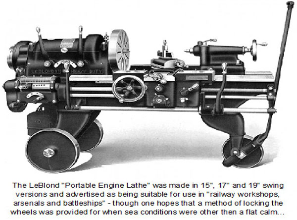
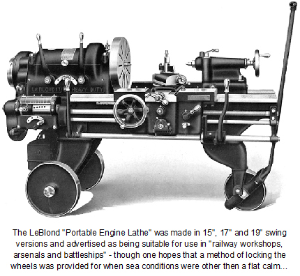
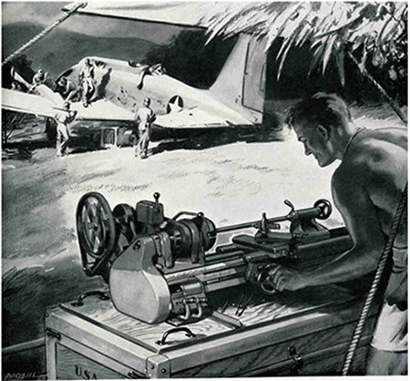
We start with a curious conventional portable lathe, on wheels of the American House Leblond Lathes – USA. Year 1931.
Its main use is developed on the railroad, arsenals and warships.
One of the first machines appeared on the market, 1903, is a portable boring bar. Curiously after 100 years the technique has not changed one iota, mechanics remains the same and the operating principle is maintained in current machines.
Photos courtesy of Transport Museum New York.
..
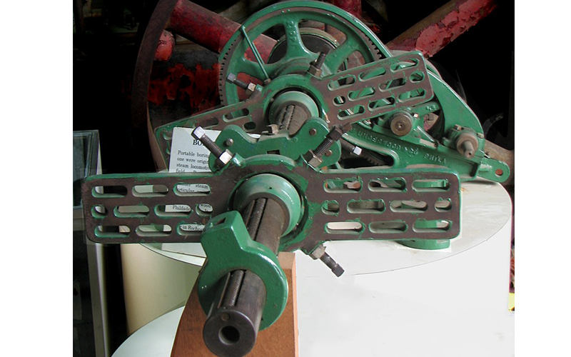
1887 portable Cylinder Boring-Machine.—shows a portable machine built by Pedrick & Ayer, of Philadelphia, especially adapted to boring out locomotive-cylinders in their places, by removing only one or both heads and piston. The back-head, cross-head, or slides need not be removed, unless so desired. On removing the piston and leaving the front head and stuffing-box, a small cone takes the place of the stuffing-box, and with proper adjustment at the front head the machine is ready for work; it is fed with a constant feed of cut-gears. The clamps or cross-heads arc so arranged that they may Ik; used conveniently on locomotive-cylinders of all sizes. The same bolts or studs that fasten the cylinder-head on are used to bolt the bar supports also. Two rods are fastened to the ends of the cross-head that supports the bar in the cylinder and to an adjustable swivel cross-head on the end of the screw; these take the whole of the thrust and torsion strain of the bar. It makes no difference which position the bar is in, the end thrust is always in line with it, causing it to cut steady, smooth, and true. The feed can be thrown out of gear at any time, and the machine will also feed automatically. Another portable boring-machine, built by Pedrick & Ayer, is designed for reboring, in present positions, all makes and sizes of steam-engine cylinders. It is so constructed that the piece being bored serves as the bed or support of the bar. The cutter heads are fed by a screw in one side of the bar, and are operated by the feed-casing on the end that contains the gearing, by changing position of which two changes can be made, slow feed for roughing out, and fast for finishing cuts. The feed is automatic and constant, or at the pleasure of the operator. The bar is driven by a train of cut gears either with a crank or belt for power.
We continue presenting historical machines that were developed to provide solutions for insitu machining.
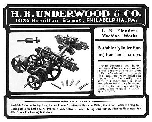
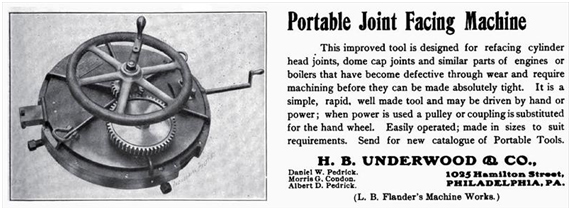
PORTABLE JOINT FACING MACHINE—The portable machine shown herewith is one that should be found useful in railroad shops and in jobbing establishments doing repairs to steam e4ngines and boilers. It is a machine for refacing cylinder head joints, dome cap joints and similar parts that have becomes leaky in service and require machining before they can be made tight once more. The machine is made up of two disks, the upper one carrying a train of gearing and a slide on which is mounted the cutting tool, and the lower one the chucking screws for screwing out against the inner walls of the cylinder counterbore or the dome ring to hold the machine in position. Two of these screws are shown in the cut. Besides the gearing shown there are three reduction gears in the space between the two disks, to reduce the speed and to give power to drive the tool. The cutting tool is mounted on a steel slide, which may be fed out automatically, or by hand. The crank seen in the illustration is for quickly moving the tool to the required position, then the feed clutch is thrown in and the crank removed, the machine feeding automatically as the handwheel is turned. The machine may be driven by hand or power; when power is employed a pulley or coupling is substituted for the handwheel. Hand power is generally used, as the time required for facing one joint is so short that it does not usually pay to connect to any other source of power. H. B. Underwood & Co., Philadelphia, are the manufacturers.
Fuente: vintagemachinery.org
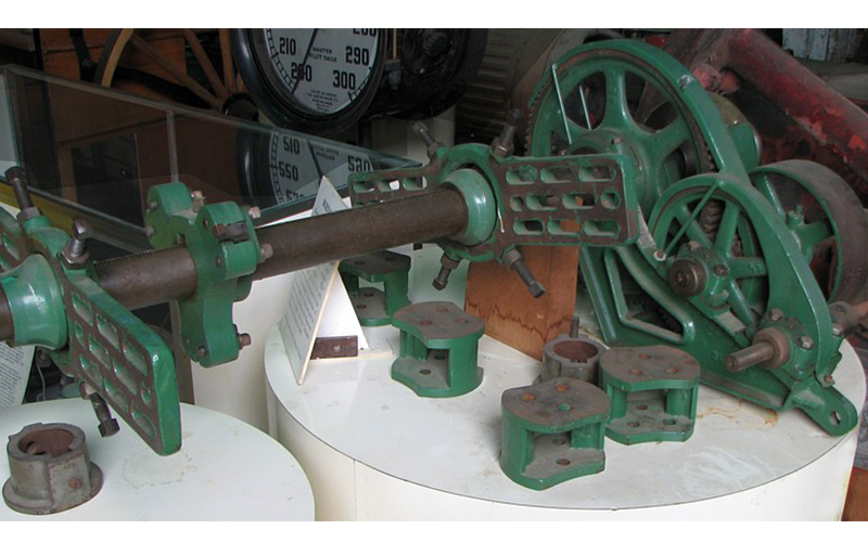
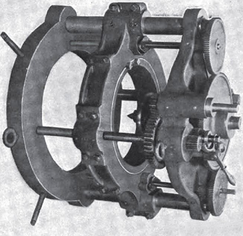
A CRANKPIN TURNING MACHINE.
One of the most difficult jobs in connection with steam engine repair work is that of re-turning large crankpins, since it is unpractical to remove them from the disks and the turning must be done in place. The cut illustrates a machine that is designed for this sort of work and is capable of turning a crank pin up to 15 inches in diameter and 12 inches long. The machine is placed over the pin with the center, shown at the right hand side, fitting the female center in the end of the crankpin. The four radial screws at the outer end of the machine are then used to adjust it properly in line with the pin, after which it is clamped to the crank by bolts and the adjusting screws are backed off out of the way of the cutter. In some pins the outer end has a tapped hole, used for bolting on a cap, and when used with such pins the center shown in the cut is replaced by a rod and bushing, which fit the tapped hole. The end of the rod projects from the center of the outer end of the machine and is clamped there by a split hub.
The cutter-head, carrying the turning tools, is held in an annular ring which revolves in a traveling head frame. On the back of the ring is cut a gear so that it may be driven by a pinion connected to the driving shaft. Upon this shaft may be mounted a pulley or grooved sheave so that the machine can be driven from any convenient belt or rope drive. Upon opposite sides of the frame that carries the cutter-head are two feed screws, which are connected at the top by suitable gears meshing with the feed gears, on the driving shaft, and thus providing for automatic feed. When finishing fillets, at the top or bottom of a pin, the automatic feed may be disconnected and the head fed by means of a crank applied to the end of one of the feed screws. The machine is the product of H. B. Underwood and Co., Philadelphia, Pa.
Fuente: vintagemachinery.org
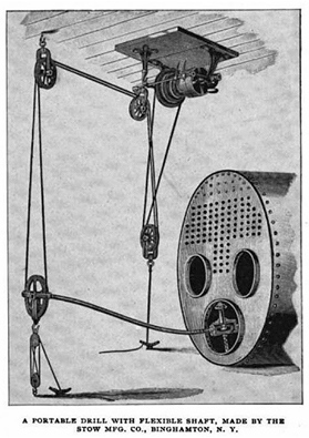
Portable Drill
Fuente: Cassier´s Magazine Dec 1896 pag 155,
Construido por: Stow Manufacturing Co., Portable Drill
In most cases, we manufactured goods but we know the construction process of the same, or we understand that it is easy to do and it does not matter how is done.
One of the jobs that less importance is usually given in the industry is drilling, if present in some cases, make holes in teams is very complicated , (dimension drill, material to drilling, drilling depth , confined spaces, explosive environments etc.) Imagine for a moment the added complexity late XVIIII century.
Here is a portable drill 1896 with pneumatic power and small size.
An ingenious machine that over the years has not changed significantly.
Source: Cassier’s Magazine Dec 1896 pg 155;
1896 Image-Stow Manufacturing Co., Portable Drill

Leave A Comment